CJ7 Wide Track Dana 30 Rebuild

PoliceMonkey161

New member
Hello All... I've had several members ask about my Dana 30rebuild, unfortunately I did not take many photo's of the strip down and gearset up, but I started taking photo's today during the re-assembly. So, let's go with that you are re-building your stock differential and are going to re-use your existing gear set up, but want to replace the bearings, races and seals.
First, here are my newly painted parts with POR-15 minus the knuckles which need extra top coat since POR-15 is UV sensitive and I missed a few spots.
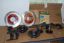
13601d1340508485t-new-project-re-building-dana-30-front-end-001.jpg

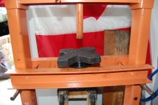
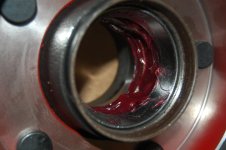
Today we will cover assembling the rotor to hub. First Iwill press the new races into the hub. Hold on to your old parts, they will come in handy. I've cleaned the inside of the hub from overspray with a"scotch pad" and put a light coat of lithium grease on the inside ofthe hub and new race. We will start with the inside of the hub.

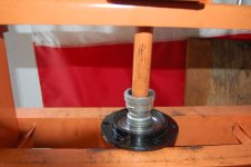
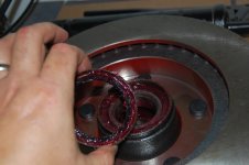
First, use a press arbor plate on the top and bottom to start the race. Next, I'll use the old bearing race on top of the new one to press intoplace. Be careful of binding, stop if parts are not square.
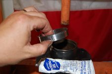
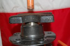
13602d1340508559t-new-project-re-building-dana-30-front-end-002.jpg


13603d1340508640t-new-project-re-building-dana-30-front-end-004.jpg

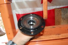
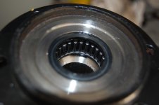
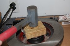
Next we will pressthe external side of the hub, same as inside with pre-cleaning and grease.However, you will need two of your old races stacked on top of each other to get it fully seated.
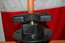
13604d1340508756t-new-project-re-building-dana-30-front-end-005.jpg

Now I cleaned up the extra grease and looked for binding or miss-alignment. In order to press the hub on to the rotor, I used new studs(but that is up to you). I started with two studs on opposite sides (I greasedthe threads only) through the rotor into the bearing. Turn the suds slightly until you feel them align with the stud groves in the hub housing. Next I applied lug nuts and tightened them slowly with a impact wrench.
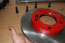
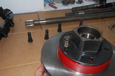
13605d1340508854t-new-project-re-building-dana-30-front-end-006.jpg


13606d1340508933t-new-project-re-building-dana-30-front-end-007.jpg

After getting the first two started, I continued to install the other three. I used a cross pattern (like installing a rim to a axle) to compress the studs. Go slow and check for miss-alignment or binding.
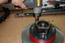
13607d1340508996t-new-project-re-building-dana-30-front-end-008.jpg

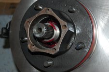
After you have fully tightened the lugs, flip over the rotor to make certain your studs are seated.
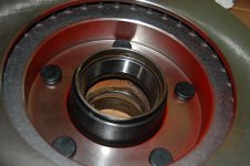
13608d1340509059t-new-project-re-building-dana-30-front-end-009.jpg


So now, you have an assembled rotor and hub!

Read more: http://www.jeepz.com/forum/cj-yj-tj-jk/39573-new-project-re-building-dana-30-a.html#ixzz1ylDjpZjY
 
Last edited by a moderator:

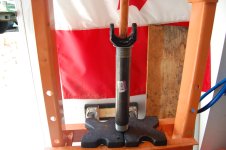
So today , I installed the inner oil seal. I started by cleaning out the socket of reside and rust using a scotch pad with a little alcohol on it.


I'm sure there as many ways and tools to do this as days in a month. However, I made a pressing tool out of a small piece of SCH 40 PVC pipe that was squarely cut and angle tapered (beveled?) the end that would be in contact with the seal face. It's a perfect fit! I pressed a steel bushing into the opposite end of the pipe.


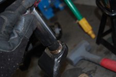
As you can see, I put a bead of RTV around the outer seal.Some manuals make reference to this and some don't. The CJ Manual by Moses Ludel recommends this and he has not lead me wrong yet! I got the started by hand,then inserted my home tool on top of it. I choose to start with the short side seal first since I knew it would be the harder of the two sides. I used an old steel broom handle as the extension the hammer the seal in place. Would have been easier with a helper!


After that is done, clean up any access sealant and check for a square fit. I used a big pipe cleaner (actually, it is a gas tube cleanerfor a M16/M4 rifle), worked out great!


Next you'll just flip over your axle and repeat. keep in mind that you will need to be careful on this side because you will be guiding your rammer pipe through the seal you just installed! The last step I did was to use my air chuck to blow out any remaining debris.

<!-- edit note -->
Last edited by PoliceMonkey161; 06-24-2012 at 09:13 PM. Reason: Typo's​
<!-- / edit note -->

Read more: http://www.jeepz.com/forum/cj-yj-tj-jk/39573-new-project-re-building-dana-30-a.html#ixzz1yvVS05Cy
 
Hello again..... Well today we are going to press in your new ball joints. Word to the wise, spend the money and get the good parts, I used Crown and they are good (OK'ish), but ran into some problems a little down the road. I did not do a write up on the removal of the joints (wish I had) because I did not think I'd be doing an article. But here's a trick for removal regardless of what method you use, soak the press fitted slots and old ball joints with PB Plaster the night before removal. It'll go so much faster for you. <o:p>
NOTE: YOUR KIT MAY INCLUDE A ZERK FITTING AND A BIG SPIT RING. ON THE NEWER DANA 30's (CJ7 STYLE ANYWAY) YOU WILL NOT BE USEING THESE.THEY ARE FOR THE EARLIER D30 AND D44's (I BELIEVE).
</o
So I started by removing over spray or debris from the socketsand put a very light coat of lithium grease on the pressing edge of the ball joint to limit any binding.
Variuos 017.JPG

<o:p></o
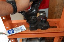
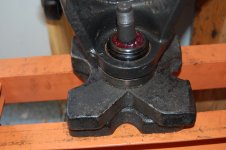
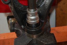
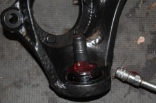
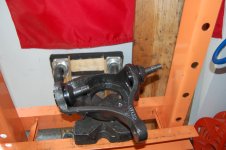
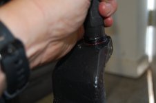
Remove the rubber boots from all the ball joints before pressing. If you are using a hydraulic press, you must start with the bottom. It pressed right in, I used a 1"X 3/4"steel coupling as my adaptor. Fit like a glove. Notice that I put one of my old bearing races under the knuckle while pressing. The ball joint will extend past the bottom of the knuckle socket during pressing.
Variuos 021.JPG

DSC_0066.JPG

<o:p></o
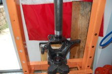
Next, I did the top, pretty much the same way include the old race as a stand (or you will un-press the bottom joint with the pressurefrom the top). I found that a 1.5" steel pipe work better on the top.
Variuos 020.JPG

<o:p></o
Them I added a little more grease to the factory ball joint,just pushed it in around the top and re-installed the rubber dust covers. Repeat on the other side and we're done!

front rebuild 002.JPG

Variuos 022.JPG
 
Last edited:
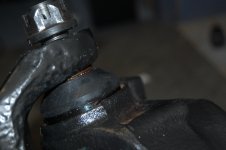
Today we are going to install our knuckles into the axle yoke. It's not hard, but remember I mentioned having problems with"Crown" ball joints earlier? Well here is where you will run into a problem, the upper ball stud split ring seat will not fit right. I re-used my old one since they still looked really good.
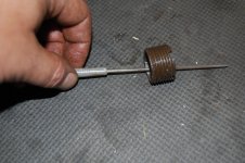
First remove any over spray and debris from threads and eyelets of the yoke. Next coat the upper split ring seat with anti-seize and run it completely through the thread hole in the yoke using a special tool (I got mine at Advance Auto, about $30), don't try to substitute a different tool like a screw driver. Just go buy the right tool, I'll see why later. Re-coat the split ring seat with anti-seize and set aside for now.
front rebuild 006.JPG

<o:p> Nevermind that the knuckle is shown installed here, it was the best picture of the tool and seat coated in anti-sieze!
This may be better?
front rebuild 003.JPG
Or this...
front rebuild 004.JPG
</o>
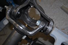
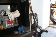
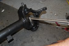
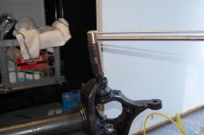
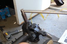
Next, install knuckle into axle. Be careful not to damage your threads. Get the bottom ball joint nut started (I used a little loctite) and tighten it up enough that the top ball joint threads are exposed. Then I used a dead blow hammer to hit the bottom of the knuckle to set it. Or you can use the two arm gear method as an alternate.
front rebuild 005.JPG


front rebuild 018.JPG
Alternate way....
front rebuild 007.JPG
<o:p></o>
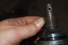
Now thread in your split ring seat, I deburied mine with a small file first and made certain it fit over the upper ball joint stud. The Crown ones do not fit correctly and getting the proper pre-load is impossible.Be sure that no anti-seize is inside the nut (it's a dry fit).
front rebuild 023.JPG


front rebuild 022.JPG
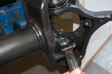
Tighten the split ring seat into the axle yoke so that just a little of its threads are showing from the bottom of the threads of the yoke,but not touching the ball joint. Tighten down the bottom ball joint nut and torque it to 85lbs. Now set your pre-load on top seat, tighten the split ring seat down to 55lbs.
front rebuild 025.JPG
front rebuild 019.JPG

front rebuild 009.JPG
<o:p></o>
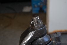
Next, install the castle nut onto the upper ball joint stud(again, I used a little loctite) and torque to approximately 100 lbs. I say approximately because you'll need to line up the castle nut to the hole in the stud for the cotter pin. Insert cotter pin, bend over tabs and your done.
front rebuild 011.JPG

<o:p></o>
Be sure to check for articulation / movement, it should tight moving side to side, but not binding.

front rebuild 013.JPG
 
Last edited:

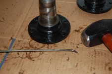
Next up is our spindle bearing replacement. This is another no of those not hard, but a P.I.T.A. things. Here is our old bearing set up.
various front end 032.JPG

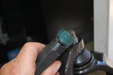
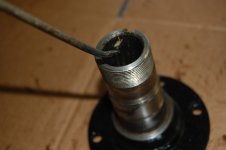
The easiser way to do this is with a polit bearing remover which you can get from Harbor Frieght Tools for about $25. But mine is on lone, so we'll go another route. I used a screw driver that I bent the tip at about 45 deg. (Craftsman, they don't care how you broke the tool).

various front end 034.JPG

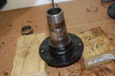
Next you simply insert the screw driver into the top of the spindle at an angle that will grab the shoulder of the bearing to be removed and hit it with a hammer. Next turn the spindle until you are on a new spot on the bear and hit it again, you contiune to just go around the bearing little by little untill it bottoms out on your work surface.
various front end 035.JPG

Next, I place the spindle on the top and between two blocks of wood to get the bearing all the way out. After that, clean out all the old grease and smooth any burring / nicks you may have caused.
various front end 036.JPG


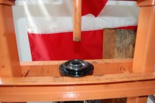
Pressing the bearing is rather smooth. Apply a light coating of lithium grease to the bearing shoulder, start it in the spindle by hand and they put an arbor press plate on top to press it further. Rememebr to go slow and check for binding or lack of squareness.

various front end 037.JPG
various front end 038.JPG

Next is the only trickly part of this whole step of our re-build, we will press the bearing inword just a little more, only enough for your bearing seal to fit on top of the bearing and flush with the top surface. You are only going to go press it maybe 1/8"? So I used my 1"X3/4" steel coupling as an adapator and just moved the bearing very slightly until it was the right depth. Caution : it is hard, if not impossble without damaging your new bearings, to go backwards or move the bearing back towards the surface. Go slow and check for depth often.

various front end 039.JPGvarious front end 041.JPGvarious front end 042.JPG
 
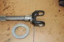
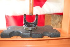
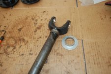
Today we are going to re-assemble our axles and install the U-joints. This was my least favorite part of this project! We will start by pressing on our oil slingers / dust shields onto each axle. Remove any overspray and debris that is still on the pressing sockets. It will be obvious that there is a difference between the inner axle slinger and the outer axle slinger. The photo shows the outer one. This part was rather hard to find (without buy a whole new axle kit), but Extremeaxlesales.com came through for me.
various front end 043.JPG

The pressing is straight forward and will go on almost by itself without pressing. But it needs to be pressed to be fully seated. Remember to use a little grease to prevent binding. Again, I used an old bearing race between the press arbor and new slinger on the outer side axle. The inner axles is the same, but I use a piece of 1.5" pipe. see photos.
<v:shape style="width: 468pt; height: 311.25pt; visibility: visible; mso-wrap-style: square;" id="Picture_x0020_4" type="#_x0000_t75" alt="various front end 044" o:spid="_x0000_i1033" coordsize="21600,21600"><v:imagedata o:title="various front end 044" src="Today%20we%20are%20going%20to%20re.docx_files/image003.jpg">
various front end 044.JPG</v:imagedata></v:shape>various front end 044.JPGvarious front end 045.JPGvarious front end 046.JPG
<v:shape style="width: 468pt; height: 311.25pt; visibility: visible; mso-wrap-style: square;" id="Picture_x0020_5" type="#_x0000_t75" alt="various front end 045" o:spid="_x0000_i1032" coordsize="21600,21600"><v:imagedata o:title="various front end 045" src="Today%20we%20are%20going%20to%20re.docx_files/image005.jpg"></v:imagedata></v:shape>
<v:shape style="width: 468pt; height: 311.25pt; visibility: visible; mso-wrap-style: square;" id="Picture_x0020_6" type="#_x0000_t75" alt="various front end 046" o:spid="_x0000_i1031" coordsize="21600,21600"><v:imagedata o:title="various front end 046" src="Today%20we%20are%20going%20to%20re.docx_files/image007.jpg"></v:imagedata></v:shape>
<o:p </o
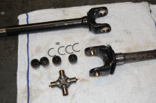
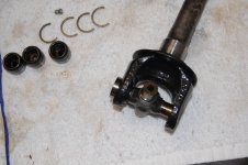
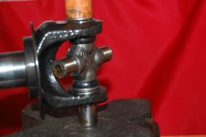
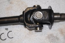
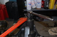
Next, I laid out my u joint pieces and remove the bearing caps from the joints (carefully). I started a cap into the outside of each axle eyelet and simply pressed the caps inward. The first photo only shows one cap in place so you would get the idea. Note the use on a drive socket under the bottom cap.

various front end 047.JPGvarious front end 048.JPGvarious front end 050.JPG
<v:shape style="width: 468pt; height: 311.25pt; visibility: visible; mso-wrap-style: square;" id="Picture_x0020_9" type="#_x0000_t75" alt="various front end 047" o:spid="_x0000_i1030" coordsize="21600,21600"><v:imagedata o:title="various front end 047" src="Today%20we%20are%20going%20to%20re.docx_files/image009.jpg"></v:imagedata></v:shape>
<v:shape style="width: 468pt; height: 311.25pt; visibility: visible; mso-wrap-style: square;" id="Picture_x0020_7" type="#_x0000_t75" alt="various front end 048" o:spid="_x0000_i1029" coordsize="21600,21600"><v:imagedata o:title="various front end 048" src="Today%20we%20are%20going%20to%20re.docx_files/image011.jpg"></v:imagedata></v:shape>
<o:p </o<o:p </o <v:shape style="width: 468pt; height: 311.25pt; visibility: visible; mso-wrap-style: square;" id="Picture_x0020_11" type="#_x0000_t75" alt="various front end 050" o:spid="_x0000_i1028" coordsize="21600,21600"> <v:imagedata o:title="various front end 050" src="Today%20we%20are%20going%20to%20re.docx_files/image013.jpg"></v:imagedata></v:shape>
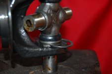
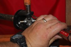
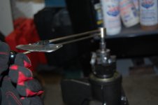
Next, we need to insert the retaining clip, I used a pair of need noise pliers to get them started and then drove them into place with a punch and hammer.
various front end 051.JPGvarious front end 052.JPG

<v:shape style="width: 468pt; height: 311.25pt; visibility: visible; mso-wrap-style: square;" id="Picture_x0020_12" type="#_x0000_t75" alt="various front end 051" o:spid="_x0000_i1027" coordsize="21600,21600"><v:imagedata o:title="various front end 051" src="Today%20we%20are%20going%20to%20re.docx_files/image015.jpg">
</v:imagedata></v:shape>
<v:shape style="width: 468pt; height: 311.25pt; visibility: visible; mso-wrap-style: square;" id="Picture_x0020_13" type="#_x0000_t75" alt="various front end 052" o:spid="_x0000_i1026" coordsize="21600,21600"> <v:imagedata o:title="various front end 052" src="Today%20we%20are%20going%20to%20re.docx_files/image017.jpg"></v:imagedata></v:shape>
Then, just repeat on other side. Check for binding and free movement in the axles at the joints. They will be stiff, but should move in all range of motion.
various front end 053.JPG


<o:p </o
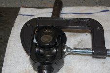
If you do not have a press or are doing just this repair in your driveway, I found that a big C clamp will do the same job.
various front end 054.JPG
<v:shape style="width: 468pt; height: 311.25pt; visibility: visible; mso-wrap-style: square;" id="Picture_x0020_14" type="#_x0000_t75" alt="various front end 054" o:spid="_x0000_i1025" coordsize="21600,21600"><v:imagedata o:title="various front end 054" src="Today%20we%20are%20going%20to%20re.docx_files/image019.jpg"></v:imagedata></v:shape>
<o:p </o
 
Last edited:
Next, let's cover installing your carrier and pinion. Unlike your rear axle, your front sees far less use, so a good inspection should serve you well and you will need only replace the parts that are worn-out (like oil seals, slingers). Well, unless you're an avivd rock crawler. Again,I am not going into great detail on the gear set up as that will be my next article. So, for whatever your motivation is (rebuild, re-gearing or just an inspection), you will need to re-install your carrier w/ ring gear and the pinion.Normally, you would measure the rotational force of the pinion prior to removal using a dial faced/ beam torque wrench in "inch lbs" prior to its removal.But not to worry, if you are using the existing bearings and races, you are looking for about 10-15 inch lbs of force without the carrier installed.

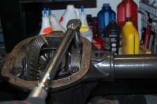
Regardless of your motivations to re-build your axle, you want to check your gears for wear, races for scoring, slingers for being straight and replace the pinion oil seal. It's much easier to do the seal while the axle is out of the jeep. The new seal will press right into the seat with a little force and a bearing race seating tool or piece of 1.5 pipe if pinion is in place (some folks like to put a little RTVaround the outside prior to installing). Next, without the carrier in place,re-install the yoke along with a new nut and washer (as usual, a little loctite), do not try to reuse the old nut and washer! You will probably need a buddy help you tighten down the yoke nut. Go slow and check your rotational force, we are looking for 10-15 lbs. with the existing bearings and races. You can always apply more force (tighten down), but you can't back it off if you over tighten it! I got mine to 12 lbs, so I'm happy.
various front end 057.JPG
various front end 058.JPG
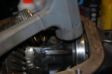
Next we will install the carrier, you do not need a spreader to do this. Use plenty of lithium grease on the races and square it up race seats inside the differential. Once it is square,use a dead blow hammer to fully seat the carrier.
various front end 060.JPG

Put your bearing caps back on, they only go on one way smoothly. If it seems rough to seat them, try flipping them over. If you look at my photo, you will see the trademarks and how they are positioned. Apply a little loctite to your bolts and tighten to 55 lbs. in a cross pattern.
various front end 061.JPG

Check for smooth turning and clean out any debris.
 
Last edited:

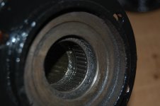
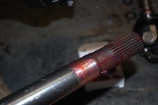
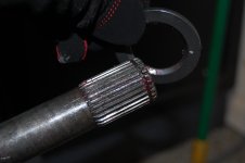
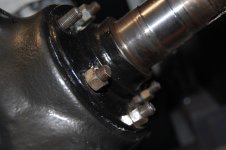
Next up, we are going to install our refurbished axles back into the differential / axle housing. Clean off any debris from the splines at the axle ends, I use a wire tooth brush. Give the splines a light coat of grease up to and around where they fit against the inner oil seal of differential (you'll see the wear marks on the ends of the axle shafts). If this area is rough, polish it with a piece of steel wool. At this point, go ahead and install your double lipped seal on the outer axle, put a light coat of grease on it. The thicker lip faces inward, see photo little down the page.
DSC_0126.JPG

<O:p>Gently guide the axle through the knuckle and down the shaft, do a little turning as you go into the seal. BE CAREFUL OF YOUR SEAL! You should feel the splines mate up with their female counter parts in the carrier. Sorry, I could not get a real good picture. Now is a good time to double check your double lipped seal for a firm fit. Next, slide on the thrust washer, note that the chamfer / beveled side faces inward. You'll notice that I coated the knuckle surface that will be in contact with the spindle with anti-seize, I also put a light coating on the spindle as well. If you have not already done so, pack your spindle bearings with grease, don't be shy with the grease!
DSC_0127.JPGDSC_0131.JPGDSC_0130.JPGDSC_0132.JPG


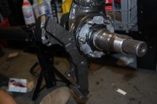
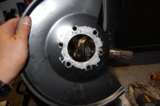
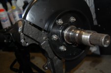
DSC_0128.JPG<O:p>Now install your spindle over the axle shaft making certain not to gall, pinch or score any of the surfaces or seals. I used a couple of old nuts to tighten down / press in the spindle. At this point, we can reattach the brake caliper brackets (be careful not to install them backwards, the arms of the brackets should be hanging over the spindle). I applied loctite to the torx's bolts and torque them to 60 lbs. Next remove your tightening bolts from the spindle and apply more anti-seize to the outer face of the spindle and the back of the brake splash guard.
DSC_0133.JPGDSC_0136.JPGDSC_0135.JPG

<O:p>Now you are ready to put your new nuts w/ lock washers or if you prefer, you could re-use your old nuts. Either way, apply loctite...... We definitely don't want these pieces working themselves loose down the road! Torque down the spindle nuts to 40 lbs.
DSC_0137.JPG

<O:p>Clean up any excess anti-seize from the parts we just installed.

***** The first photo below (thumbnail) is to show the incorrect way to apply the Torx's bolts, note that they are intalled from the outside inward and the bracket is on the outside.It's a common mistake******

The second thumbnail just loaded all by itself?
</O< o< html>
 

Attachments

  • DSC_0134.JPG
    DSC_0134.JPG
    1.5 MB · Views: 94
  • various front end 065.JPG
    various front end 065.JPG
    1.5 MB · Views: 82
Last edited:
Now we are ready for the messy part, installing the rotor /hub assembly and bearing. Take your time doing these next few steps, if you get your parts mixed up or don't use enough grease you've pretty much wasted your time!
Let's start with filling the gap or area (the"void") between the bearing races inside your rotor with grease. You will be literally building a damn of grease. VERY IMPORTANT: I failed to mention early that each wheel / outer axle assembly has two bearings and races,one on the inside and the other on the outside. These bearings / races are different sizes! The races are the same outside diameter and can be easily mixed up! The bearing with the smaller inside diameter and shorter race goes on the outside. Take a minute and match your parts....... The bearings are self explanatory as they will only fit on the spindle in the correct order, but if the races are reversed the rotor/hub will go on....But you will never get the axle to extend out enough to put the split ring back on. Plus, the rotor will feel like it is binding if you turn it.
DSC_0138.JPG

<O:p></O>
Next drop in your inside bearing (pack in good with grease!)and fill around the outside and top of the bearing surface with more grease.Now, carefully put your grease seal on. There are many brand of seals that all look different and they can be confusing.....So, looking at your seal, there is a rubber seal that is tapered, cone shaped or shaped like a chevron. It gets installed into the hub body with that tapered seal towards the bearing....So it will slide and seal against the spindle. If you're lucky and have"National Oil Seal" brand, they have a solid steel back which will face the spindle side. If you're not sure, try dry fitting the seal on the spindle and you should see what I'm getting at here. Grease up the inside of the seal. Seat it in place on the back of the hub and put a piece of wood on top of the seal. Gently hit it with a hammer to set it.
DSC_0139.JPG
DSC_0140.JPG
<O:p></O>
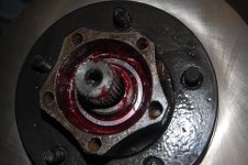
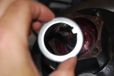
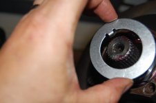
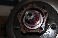
Now carefully slide the rotor assembly onto the spindle until it is fully seated against the spindle. Next, insert your outer bearing(pack it with grease prior to installing), fill the top and outside of the bearing surface with more grease. First you put on the smaller"tabbed" washer in, then the first nut. Tighten down the first nut (while turning the rotor, a helper isuseful) to 50lbs of torque, then back it off about a 16th to an 8th of a turn.Next slide in the larger "tabbed" washer and the second nut. Tighten that down to 50-55lbs. without backing it off. I know some of you will disagree with me, but I don't bend the locking tab until I'm sure everything (like the locking hub assembly) fit. Fill any voids around the nut with more grease!
DSC_0142.JPGDSC_0143.JPGDSC_0144.JPGDSC_0145.JPGDSC_0146.JPG
DSC_0147.JPG

<O:p></O>
At this stage, I will install our new differential / axlehousing onto the jeep. I'll hold off on the locking hubs until later as they are easily damaged during the differential install.
<O:p></O>
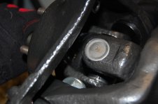
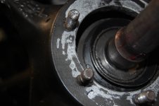
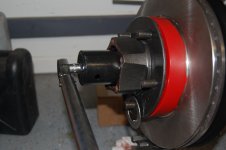
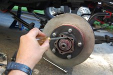
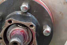
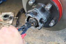
Once the differential / axle is installed, I like to dry fit my locking hubs and make sure I have enough clearance to get the snap ring on. If your axle is being bashful and does not want to come all the way out, gently use a pry bar between the U-joint and leverage it forward. If it looks good, go ahead and bend your locking tab down. I use the bent tipped screw driver from the spindle job for this. BE CAREFUL NOT TO HIT THE BEARING CAGE WHILE DOING THIS! After you get it started forward, use a punch and hammer to flatten it against the outer spindle nut. Note that I put on a set of lug nuts, I do this to protect the threads and it keep the vibrations from the impact wrench from lossening my pressed fittings. Later in our job, you will see that they will also serve as a leverage point for tightening down the hub body.
DSC_0161.JPG
DSC_0162.JPG
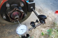
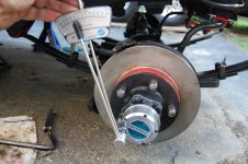
Lastly, we will set up our dail caliper and check for end play.......... It should be zero!
DSC_0163.JPG
 
Last edited:
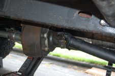
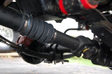
Today, we are going to finish up our install of our newly rebuilt Dana 30 Front End. As some of you recall from my other posting, I had serve trouble with my front drive shaft. It became frozen in place from improper maintenance by the previous owner. I choose to upgrade to a "Tom Woods" custom drive shaft with a sealed boot around the splines. A quick call to Tom Woods with my measurements (Don't worry if you're not sure about how to get this, they will walk you through getting the correct length). Oddly enough, the custom shaft is less expensive than the OEM replacement and it's constructed from 2" tubing rather than the stock 1.25".
A few days later, this fine piece of art work arrived at mydoor, it bolted right up with absolutely no problems!
various 015.JPGvarious 016.JPG

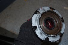
So, next we will install our hubs, I choose to use"Super Winch" (most of the aftermarket hubs pretty much go on the same way) or you can re-use your factory hubs. The factory hubs are good in my opinion, but way over designed. Most hubs must be in 4X2 to install, if you're not sure check with your manufacture! Apply some anti-seize to the face of the rotor/huband to the base gear of your locking hub. Place the gasket between the two.
DSC_0164.JPG

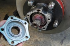
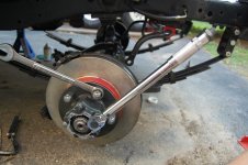
Next re-install your five (or six if you have the older style hubs) bolts to secure the hub locking gear to your rotor/hub, torque to about 35-40lbs. Note the use of the box wrench on the lug nuts to get leverage.Now you're ready to put on the end split ring (Remember the trick with the prybar to get it extended fully!)
DSC_0166.JPG
DSC_0165.JPG
Now apply a little anti-seize to the hub locking cap/selector and install the five (or how many your brand has) small assembly bolts. With Super Winch Hubs, torque them to 25-30 inch. lbs in a cross pattern.
DSC_0167.JPG

Check to make sure your new hubs lock and unlock as designed by turning the selector to 4X4, then back to 4X2. You may need to turn the rotor in order to get them to engage and disengage. I like to trim any of the paper gasket that is sticking out with a razor knife. The excess material will attract moisture during normal and off-road use.
various 017.JPG

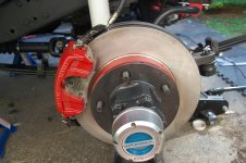
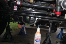
<o:p>After re-connecting the tie rods and drag link, the calipers and pads and vent tube (Very important! First puddle without a vent tube and you will have a contaminated carrier assembly). We need to add the gear oil, depending on the ratio and/carrier upgrade you will need about 2-2.5 pints of gear oil. I like mixing my differential oil with 50/50 of Lucas Oil Stabilizer and gear oil, especially for the brake-in period. Note that I re-attached the Dana factory nomenclature/tag to the front of the diff. I engrave the backside of the tag with the date of rebuild and if I changed gear ratios.
various 018.JPG


Now let's re-check all of our fittings, hose's, grease up any new zerks and look for anything that may be loose! Lastly install your tires and take it for a very short ride around the block work through your front gears and locking/unlocking the hubs checking for leaks and smooth movement. Next, off to the alignment shop!....We are done!

Believe it or not, If had re-used my factory or existing equipment, I would have kept my cost under $350 which included my re-alignment.I did up grade my tie rods and drag link to the Rugged Ridge Heavy Duty model which was separate and cost me an additional $205. The Tom Woods driveshaft was an additional $240 including "Gold Seal U-joint" delivered to my door! </o
 
Last edited:

Quick update!<o:p></o:p>
I would not recommend the purchase/use of “Crown” Ball Joints. This brand is found as the OEM style replacements at Morris 4X4 and Quadartec. This statement is not in meant to be a criticism in any way of either retailer! They are both very trusted sources of parts.………. Mine failed after a month or about 500 miles. As I stated earlier in this article, I had problems getting the preload split ring to fit. For record, the NAPA store brand fit prefect and cost half as much.
 
Back
Top