need help with 30 amp fuse / asd relay

unhappy

well the new cam sensor was put in..... and the cam & crank sensor are still out of sync... they over lap but not just right... so the coils are still on too long and over heat.... so it's the timing they tell me .... it's a tooth or less is how far it is off.. they only do electrical stuff so they would check the timing... the local place they said is good wants 1300$ to replace the 3 chains and tensinors... ummmm no

so my hope is that when it gets home.. i pull off the cam/valve covers.. turn it over to tdc on the timing cover mark and see that it might have skiped and is one tooth off.... if not i'm very perplexed cause if the timing marks line up.. it should run.... as it does not but with out any problems right????

help........
 
If that is equipped with a cam phaser on the camshaft, there's a procedure that needs to be followed to a tee to ensure proper timing.
 

If that is equipped with a cam phaser on the camshaft, there's a procedure that needs to be followed to a tee to ensure proper timing.


cam phaser... yes.... just replaced

too double check my timing what is the correct procedure??? and what do i do if the all the marks line up????

thanks....
 
The timing drive system has been designed to provide quiet performance and reliability to support a non-free wheeling</B> engine. Specifically the intake valves are non-free wheeling and can be easily damaged with forceful engine rotation if camshaft-to-crankshaft timing is incorrect. The timing drive system consists of a primary chain and two secondary timing chain drives .

808a1e65-3.gif

1 - RIGHT CAMSHAFT SPROCKET AND SECONDARY CHAIN 2 - SECONDARY TIMING CHAIN TENSIONER (LEFT AND RIGHT SIDE NOT COMMON) 3 - SECONDARY TENSIONER ARM 4 - LEFT CAMSHAFT SPROCKET AND SECONDARY CHAIN 5 - CHAIN GUIDE 6 - TWO PLATED LINKS ON RIGHT CAMSHAFT CHAIN 7 - PRIMARY CHAIN 8 - IDLER SPROCKET 9 - CRANKSHAFT SPROCKET 10 - PRIMARY CHAIN TENSIONER 11 - TWO PLATED LINKS ON LEFT CAMSHAFT CHAIN 12 - SECONDARY TENSIONER ARM

The primary timing chain is a single inverted tooth type. The primary chain drives the large fifty tooth idler sprocket directly from a 25 tooth crankshaft sprocket. Primary chain motion is controlled by a pivoting leaf spring tensioner arm and a fixed guide. The arm and the guide both use nylon plastic wear faces for low friction and long wear. The primary chain receives oil splash lubrication from the secondary chain drive and oil pump leakage. The idler sprocket assembly connects the primary and secondary chain drives. The idler sprocket assembly consists of two integral thirty tooth sprockets and a fifty tooth sprocket that is splined to the assembly. The spline joint is a non – serviceable press fit anti rattle type. The idler sprocket assembly spins on a stationary idler shaft. The idler shaft is press-fit into the cylinder block. A large washer on the idler shaft bolt and the rear flange of the idler shaft are used to control sprocket thrust movement. Pressurized oil is routed through the center of the idler shaft to provide lubrication for the two bushings used in the idler sprocket assembly.
There are two secondary drive chains, both are inverted tooth type, one to drive the camshaft in each SOHC cylinder head. There are no shaft speed changes in the secondary chain drive system. Each secondary chain drives a thirty tooth cam sprocket directly from the thirty tooth sprocket on the idler sprocket assembly. A fixed chain guide and a hydraulic oil damped tensioner are used to maintain tension in each secondary chain system. The hydraulic tensioners for the secondary chain systems are fed pressurized oil from oil reservoir pockets in the block. Each tensioner also has a mechanical ratchet system that limits chain slack if the tensioner piston bleeds down after engine shut down. The tensioner arms and guides also utilize nylon wear faces for low friction and long wear. The secondary timing chains receive lubrication from a small orifice in the tensioners. This orifice is protected from clogging by a fine mesh screen which is located on the back of the hydraulic tensioners.
NOTE: The blue link plates on the chains and the dots on the camshaft drive sprockets may not line up during the timing verification procedure. The blue link plates are lined up with the sprocket dots only when re-timing the complete timing drive. Once the timing drive is rotated blue link-to-dot alignment is no longer valid.


Engine base timing can be verified by the following procedure:
  1. Remove the cylinder head covers .
  2. Using a mirror, locate the TDC arrow on the front cover . Rotate the crankshaft until the mark on the crankshaft damper is aligned with the TDC arrow on the front cover. The engine is now at TDC.
  3. Note the location of the V8 mark stamped into the camshaft drive gears . If the V8 mark on each camshaft drive gear is at the twelve o'clock position, the engine is at TDC (cylinder #1) on the exhaust stroke. If the V8 mark on each gear is at the six o'clock position, the engine is at TDC (cylinder #1) on the compression stroke.
  4. If both of the camshaft drive gears are off in the same or opposite directions, the primary chain or both secondary chains are at fault. Refer to Timing Chain and Sprockets procedure in this section.
  5. If only one of the camshaft drive gears is off and the other is correct, the problem is confined to one secondary chain. Refer to Single camshaft timing, in this procedure.
  6. If both camshaft drive gear V8 marks are at the twelve o'clock or the six o' clock position the engine base timing is correct. Reinstall the cylinder head covers.
SINGLE CAMSHAFT TIMING


NOTE: to adjust the timing on one camshaft, preform the following procedure.
  1. Using Chain Tensioner Wedge, special tool 8350, stabilize the secondary chain drive . For reference purposes, mark the chain-to-sprocket position.
  2. Remove the camshaft drive gear retaining bolt.
  3. Carefully remove the camshaft drive gear from the camshaft.
  4. Re-index the camshaft drive gear in the chain until the V8 mark is at the same position as the V8 mark on the opposite camshaft drive gear. NOTE: When gripping the camshaft, place the pliers on the tube portion of the camshaft only. Do not grip the lobes or the sprocket areas.
  5. Using a suitable pair of adjustable pliers, rotate the camshaft until the alignment dowel on the camshaft is aligned with the slot in the camshaft drive gear . CAUTION: Remove excess oil from camshaft sprocket retaining bolt before reinstalling bolt. Failure to do so may cause over-torqueing of bolt resulting in bolt failure.
  6. Position the camshaft drive gear onto the camshaft, remove oil from bolt then install the retaining bolt. Using Special Tools, Spanner Wrench 6958 with Adapter Pins 8346 and a suitable torque wrench, Tighten retaining bolt to 122N·m (90 ft. Lbs.)
  7. Remove special tool 8350.
  8. Rotate the crankshaft two full revolutions, then reverify that the camshaft drive gear V8 marks are in fact aligned.
  9. Install the cylinder head covers
INSTALLATION

  1. Using a vise, lightly compress the secondary chain tensioner piston until the piston step is flush with the tensioner body. Using a pin or suitable tool, release ratchet pawl by pulling pawl back against spring force through access hole on side of tensioner. While continuing to hold pawl back, Push ratchet device to approximately 2 mm from the tensioner body. Install Special Tool 8514 lock pin into hole on front of tensioner. Slowly open vise to transfer piston spring force to lock pin .Position primary chain tensioner over oil pump and insert bolts into lower two holes on tensioner bracket. Tighten bolts to 28 N·m (250 in. lbs.).
  2. CAUTION: Overtightening the tensioner arm torx® bolt can cause severe damage to the cylinder head. Tighten torx® bolt to specified torque only.
  3. Install right side chain tensioner arm. Apply Mopar® Lock N, Seal to torx® bolt, tighten bolt to 17 N·m (150 in. lbs.). NOTE: The silver bolts retain the guides to the cylinder heads and the black bolts retain the guides to the engine block.
  4. Install the left side chain guide. Tighten the bolts to 28 N·m (250 in. lbs.). CAUTION: Overtightening the tensioner arm torx® bolt can cause severe damage to the cylinder head. Tighten torx® bolt to specified torque only.
  5. Install left side chain tensioner arm. Apply Mopar® Lock N, Seal to torx® bolt, tighten bolt to 17 N·m (150 in. lbs.).
  6. Install the right side chain guide. Tighten the bolts to 28 N·m (250 in. lbs.).
  7. Install both secondary chains onto the idler sprocket. Align two plated links on the secondary chains to be visible through the two lower openings on the idler sprocket (4 o'clock and 8 o'clock). Once the secondary timing chains are installed, position special tool 8515 to hold chains in place for installation .
  8. Align primary chain double plated links with the timing mark at 12 o'clock on the idler sprocket. Align the primary chain single plated link with the timing mark at 6 o'clock on the crankshaft sprocket.
  9. Lubricate idler shaft and bushings with clean engine oil.
  10. Install all chains, crankshaft sprocket, and idler sprocket as an assembly . After guiding both secondary chains through the block and cylinder head openings, affix chains with a elastic strap or the equivalent, This will maintain tension on chains to aid in installation. NOTE: It will be necessary to slightly rotate camshafts for sprocket installation.
  11. Align left camshaft sprocket “L” dot to plated link on chain.
  12. Align right camshaft sprocket “R” dot to plated link on chain. CAUTION: Remove excess oil from the camshaft sprocket bolt. Failure to do so can result in over-torque of bolt resulting in bolt failure.
  13. Remove Special Tool 8515, then attach both sprockets to camshafts. Remove excess oil from bolts, then Install sprocket bolts, but do not tighten at this time.
  14. Verify that all plated links are aligned with the marks on all sprockets and the “V8” marks on camshaft sprockets are at the 12 o'clock position . CAUTION: Ensure the plate between the left secondary chain tensioner and block is correctly installed.
  15. Install both secondary chain tensioners. Tighten bolts to 28 N·m (250 in. lbs.). NOTE: Left and right secondary chain tensioners are not common.
  16. Before installing idler sprocket bolt, lubricate washer with oil, and tighten idler sprocket assembly retaining bolt to 34 N·m (25 ft. lbs.).
  17. Remove all locking pins (3) from tensioners. CAUTION: After pulling locking pins out of each tensioner, DO NOT manually extend the tensioner(s) ratchet. Doing so will over tension the chains, resulting in noise and/or high timing chain loads.
  18. Using Special Tool 6958, Spanner with Adaptor Pins 8346, tighten left and right . camshaft sprocket bolts to 122 N·m (90 ft. lbs.).
  19. Rotate engine two full revolutions. Verify timing marks are at the following locations:
    • primary chain idler sprocket dot is at 12 o'clock
    • primary chain crankshaft sprocket dot is at 6 o'clock secondary chain camshaft sprockets “V8” marks are at 12 o'clock
  20. Lubricate all three chains with engine oil.
  21. After installing all chains, it is recommended that the idler gear end play be checked . The end play must be within 0.10–0.25 mm (0.004–0.010 in.). If not within specification, the idler gear and idler shaft must be replaced.
  22. Install timing chain cover and crankshaft damper.
  23. Install cylinder head covers .NOTE: Before installing threaded plug in right cylinder head, the plug must be coated with sealant to prevent leaks.
  24. Coat the large threaded access plug with Mopar® Thread Sealant with Teflon</B>, then install into the right cylinder head and tighten to 81 N·m (60 ft. lbs.) .
  25. Install the oil fill housing.
  26. Install access plug in left cylinder head
 
Last edited:
Thanks Steelheadz, I will be heading up to tow hooks house in the morning and (if he hasn't checked yet) will tell him to jump on and check it out.
 

awwaa the time is ???? the main chain idle sprocket was checked to make sure the marked links were in the correct windows... how ever... i don't recall the marks on the primary chain... i printed out the valve timing chapter ( 9-141 ) of the d/c service manual.. and it goes in greater depth... so i'll compare the hanes manual vs what i read here.. thanks...

i bet it comes down to, i shoulda replaced the chains from the get go....:x

thanks again...
 
i'm pulling my hair out

is it done yet... nope...

ok we advanced the timing, cause the dots were a tooth off, well we went the wrong way.... so we alinged it as per the v 8 marks @ 12 O'CLOCK....

and now it won't idle and shuts off like it has a lack of fuel........ the pass side tensior is very strong... the driver's side not so strong... but it revs with out flutter.. :) we ran it with the cam covers off idled great wrapped it up to go for a ride... now a loping idle...

so after setting it 2 times today i'm done:x and need to walk away... i'll pull the cam cover's sunday and if it skipped i'm assuming so .. if so i will throw on the new chains.... and tensoners next week some time.. after i get a garage back from tearing down the 62 willys....

what keeps the chains from skipping before the hydrolic part of them are filled, just the spring holds it tight???

finish one project before ya start anouther....:lol:
 

awaaaa almost there........ been 3 months.....

ok the dow pins in the cam were mushroomed from some friends trying to help reset the timing... 1 week at the machine shop to get them replaced

then the rocker arm/ follower was not seated, and cam out when the timing was rest... cracked the head.... got a new head, and tricked out again..........

my garage is cursed... and i will not longer work on it.....nor do i have the heart or time... being busy at work.....

So it's @ the dealer getting new chains, and the head replaced.... should be done next week....
 
now done

ok been for ever... but it has ended... the asd reply was blowing due to the timing, the main chain was 2 links off......

the chains have been replaced, and all tensioners..... does it run... oh ya.... the 3:73 need out and some 4:10's need in.. but first to fix the rubbing issue..... needs more lift...

in adjusting the front control arms the driver lower was siezed bad... took heat and a large pipe wrench to heat off, and back on.. the other arms were anti seized the same way no issues... but a call to bds and my local 4wd shop.. www.ok4wd.com and a new arm was to my door in 3 days ...

i wish bds made rear arms for her jeep.. cause i would buy those...

thanks for all the help steel headz

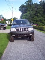
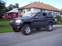
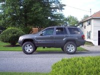
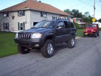
and the finished jeep.. pics of course.... :)
 

Attachments

  • new wheels 1.jpg
    new wheels 1.jpg
    137.5 KB · Views: 899
  • new wheels 2.jpg
    new wheels 2.jpg
    79.8 KB · Views: 848
  • new wheels 3.jpg
    new wheels 3.jpg
    92.1 KB · Views: 677
  • new wheels 4.jpg
    new wheels 4.jpg
    78.1 KB · Views: 1,579
Any update on what fixed this monster? Cause I have the exact same problem. Post head gasket repair too. Got to be it's brother I'm working on.
 
Back
Top